Doug Kerr
Well-known member
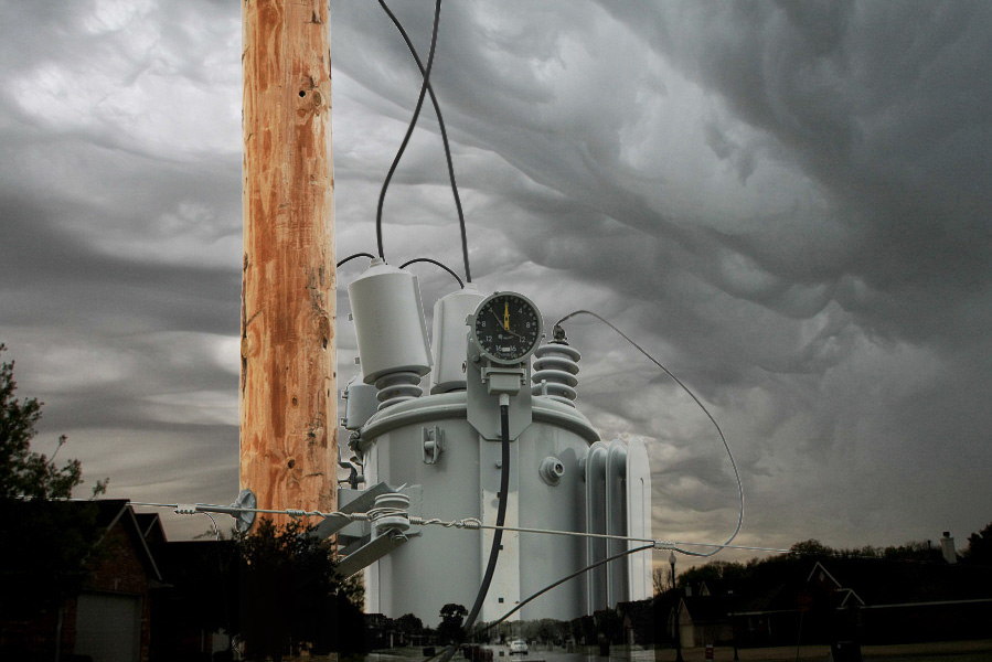
I took this shot for technical reasons only (so I could identify this apparatus), but when I looked at it on-screen, I was taken by the beautiful tones of the pole (almost brand new) and its contrast with the apparatus, and also by the accidental "high-key" look (the overcast sky almost blew out of its own accord).

This is a GE single-phase voltage regulator on a three phase distribution line into a rural area (there are three of them in the installation, on successive poles, probably 132 feet apart - no sense putting poles where you don't need them!)
These units are automatic tap-changing autotransformers. Their role is to send the power on its way at a "standard" voltage notwithstanding variations in the arriving voltage (caused by varying voltage drop due to loads along the line before this point).
The little "speedometer" dial on the top shows the current position of the tap changer and thus the transformer ratio. The 12 o'clock position we see indicates that the transformer is currently operating at 1:1 - the voltage sent along is the same as the voltage arriving. Each little bump on the scale represents an increment in ratio of 5/8% (of 1:1).
The little gray hands are pushed by the yellow hand, and serve to show the extremes of ratio (in the "raise" and "lower" directions) that have been called for since the hands were last reset (which is done electromagnetically from the control unit located at the bottom of the pole).
This is the full frame (downsampled). The only post processing was a little fiddling with the curves to fully blow out the background (although visually you couldn't really notice) and some sharpening after downsampling.