• Please use real names.

    Greetings to all who have registered to OPF and those guests taking a look around. Please use real names. Registrations with fictitious names will not be processed. REAL NAMES ONLY will be processed

    Firstname Lastname

    Register

    We are a courteous and supportive community. No need to hide behind an alia. If you have a genuine need for privacy/secrecy then let me know!
  • Welcome to the new site. Here's a thread about the update where you can post your feedback, ask questions or spot those nasty bugs!

Canon 1D3 dynamic range test results

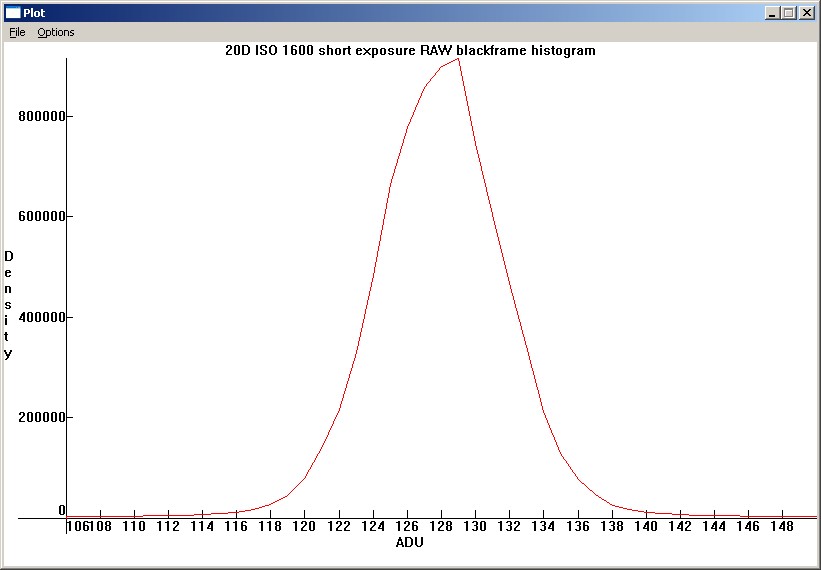
Oh, I forgot, the blackpoint is 1024 to 1025 ADU for the 1Dmk3.

Which only feeds my scepticism, it's a 3 bit difference (128 x 2^3 = 1024). There is no sense in not utilizing the LSBs in Raw data by the camera's ADC. It looks suspiciously like a scaling issue, not the real data.

Now that I think of it, your complaint about the blackpoint came back to my mind. Did you not like the fact that the black level was not zero?

Correct, because it doesn't make sense (for Raw sensor data), and other software doesn't have a 128 blackpoint level in its output.

Clipping to zero is not optimum. Subtracting the black point is useful, and IRIS maintains the negative numbers, which are very useful. If you are going to do any kind of downsampling, binning, white balancing, or "demosaicing" (I don't think any of IRIS' methods are true demosaicing; they are just interpolations), it is best to do them with the negative numbers unclipped (you can actually do all of them except WB before subtracting the blackpoint).

The Raw quantized data from the ADC is not clipped, and there are no negative counts of electrons, that is all postprocessing. All the ADC does is is convert the electron charge to discrete numbers on a scale from 0-4095 in 12-bits space, and it avoids the highest saturation values (max. ~3584 in 12-bit space on my 1DsMk2, depending on channel and ISO). Do note that it takes a camera like the 1D(s) Mark II up to (depending on channel) 20 electrons between subsequent 12-bit Digital numbers, due to the ADC gain settings at ISO 100. It is only at High ISO settings that we reach Unity Gain levels with a 1 electron difference between Digital Numbers (which obviously marks the highest useful ISO/Analog Gain) for Raw files.

Bart
 

John Sheehy

New member
Let me tell you frankly that I am very sceptical about that 128 blackpoint level. First reason is that it is mathmatically/physically unlikely to have no signal in the Least Significant Bits (LSBs).

There's at least some signal in all the bits. Having an electrical bias equivalent to 128 ADU doesn't change that. It just moves "zero light" to 128 (or 256 or 1024). It's definitely real. It's the center of the noise histogram. Do a histogram of a blackframe in IRIS, zoomed into the black level, like this from my 20D at ISO 1600 at 1/8000:

original.jpg


You don't think that the left half of the gaussian curve is fabricated do you? It's really there, in the RAW file. There's an electrical bias on the signal, and negative as well as positive noise is present in the RAW file. That is a good thing, if you know how to use the negative noise to your advantage. If left in before binning, downsampling, and white-balancing, it increases the shadow S/N a tiny bit, and the shadow noise is interpreted slightly less chromatic, and keeps the deep shadows closer to linearity (they are totally linear based on area before black-clipping). Clipping at black causes non-linearity in the deepest shadows, and the earlier in your RAW conversion that you clip the blackpoint, the more non-linearity and noise you have in the deep shadows.

Second reason is that ImagesPlus gives 16-bit values of 0, 16, 32, 48, ... for the blackframe's Green channel, which obviously is 0, 1, 2, 3, ... in 12-bit space.

If the highest population is at 0, and by a large margin, then the program has already clipped black at 128 and made everything from 0 to 128 become 0.

The other channels have values of Red 0, 36, 73, 110, ... and Blue 0, 20, 40, 60, ... which are all linear slopes before color balancing.

Do you mean that you have 0, 36, 73, etc before color balancing? If that is the case, the software has already performed a preliminary color balance. All color channels have the same values in a RAW file, even if the color channels were digitally manipulated or amplified in a different manner.

The third reason is that it just doesn't make sense to not use the LSBs.

They are being used. 0 in the RAW data means -128, 1 means -127, 127 means -1, 128 means 0 (black), 129 means 1, 130 means 2, and 4095 means 3967. It's not really about using "bits"; it's about using levels, which just happen to be stored as bits of varying magnitude for efficiency.

That does make sense, as does the limiting of the highest saturation Digital Number by Canon, to reduce blooming/fringing artifacts in postprocessing.

CMOS sensors don't bloom. Canon does not protect the 10D from going into sensor saturation at ISO 100, and all it does is get non-linear, and allow an extra 1/3 stop of highlights to be rolled in non-linearly. And of course, the lowest ISO is there only one where you could potentially digitize
the saturation zone of the sensor.
 
Actually for now I would love to just figure out how to build a lightroom preset for my DMR that looks good. None of the calibration scripts that I have tried are giving me results that look good or are accurate.

Adobe uses its own proprietary native camera color space 'profiles'/look-ups, and doesn't allow for user generated input profiles, other than by tweaking theirs.

That is a difficult way of solving color rendering issues, but creating quality ICC profiles (while standardized) are no simple exercise either. At least the ICC profiling is an open system which allows exellent colors in e.g. Capture One (especially with third party e.g. Magne's profiles).

The lack of User input ICC Profile selection in ACR is just too bad, because ARC is becoming a very useful tool otherwise, with e.g. very useful highlight recovery. Maybe a tool like Gamutvision can assist in improving the calibration trial-and-error tweaks?

Bart
 

Eric Hiss

Member
ACR lightroom calibration

Hi Bart,
I've never used Gamutvision but will take a look. I have been using the imatest colorcheck function to see how close i am getting. I hope this is not too far off topic but I wonder if you could point me in the right direction.

I want to build a preset with the color tweak values for Lightroom based on shots of the macbeth colorchecker. My idea is to first build a tone curve that brings the (white balanced) grey patches to the correct average values, then tweak the input color settings to get as good a color match as I can. I've tried Tom Fors scripts, Tindeman's and Rag's as well. None of them are really working and all three yield disparate settings. I believe I will need to do this by eye, then check with the Imatest color check to see how close I got. Now here's where you may be able to help. What would be awesome is if I could know how the color patches would change if say I adjusted the blue hue setting positive, and so on. Probably basic color stuff and maybe you or someone else knows of a link to the information? THat way I could take the delta info from the colorcheck and then make educated adjustments on the second pass, and so on.

Does that make sense?

Thanks,
Eric
 
I want to build a preset with the color tweak values for Lightroom based on shots of the macbeth colorchecker. My idea is to first build a tone curve that brings the (white balanced) grey patches to the correct average values, then tweak the input color settings to get as good a color match as I can. I've tried Tom Fors scripts, Tindeman's and Rag's as well. None of them are really working and all three yield disparate settings.

Wouldn't it be easier to base your preferences on the e.g. Tom Fors script results, or are they creating something completely out of wack?
By the way, this article, and the discussion at the bottom of that page, may be of some help. These scripts essentially do automatically what you intend to do by hand. To me it seems quicker to start with the script results. Here is a suggestion to run the Fors script under CS3, if it is not yet updated by now.

I believe I will need to do this by eye, then check with the Imatest color check to see how close I got. Now here's where you may be able to help. What would be awesome is if I could know how the color patches would change if say I adjusted the blue hue setting positive, and so on.

For that you'd need to know the spectral composition of some of the color patches and the color of the lightsource, and a pretty good knowledge of color profiling. Even then it would be a daunting task. However, the MacBeth Colorchecker does have a Red, Green, and Blue patch to get to a sense of direction with regards to the RGB color channels. You may want to slightly change the saturation of those, and verify the effect in Imatest/Gamutvision. When on the other hand you change their Hues, the White balance will most certainly shift a considerable amount, so I recommend to initially play with the Saturation instead. Given the scripted baseline, greys/grays should stay 'relatively' neutral. After that you can tweak the CMY patch saturations.


Probably basic color stuff and maybe you or someone else knows of a link to the information? THat way I could take the delta info from the colorcheck and then make educated adjustments on the second pass, and so on.

I don't think there is a direct/simple relationship between the deltas and the required correction to eliminate them, it's more likely a means to quantify the effect of a given iterative change. Only change 1 variable at a time.

That being said, don't forget the remarks of Andrew Rodney in the comments part of Martin Evening's article, accurate color is not necessarily pleasing color (although I may add, it is a good starting point for pleasing color which is just a deliberate deviation from accurate).

Bart
 
Okay John,

I now see what you mean. The histogram helped, although the one I get from a 20D file in IRIS looks much less detailed, with just a peak at 128 due to an offset.

You don't think that the left half of the gaussian curve is fabricated do you?

Well, you could have fooled me into thinking just that, with the discontinuity in the curve and al. It looks like a totally synthetic left half of a Gaussian below 128. I'm not saying that it would be useless in postprocessing, but it looks fabricated indeed.

It's really there, in the RAW file.

In the DCRAW conversion output, or in the Raw file itself? Do you have a source for that?
The reason I ask, is because the Canon Raw files are basically a TIFF file with unsigned binary numbers for the Raw data. So If you have better/different info, it would help to understand where this offset comes from.

A Raw conversion in ImagesPlus from my 20D produces an ISO 1600 Read-Noise (Lens and viewfinder covered, 1/8000th of a second exposure) histogram, at 18 degrees Celcius for the Green sensels only, that looks like this:

Histo_20D_ISO1600_12bitsG.png

Histogram taken from FITS data converted to 12-bits in ImageJ

To me that makes sense, because the initial electrons are also counted starting from a Reset quantity, one by one. There is no negative noise, it all adds (in this case 0 electrons + read noise). There is no other distribution than a Poisson distribution for these processes, which also have no negative numbers.

There's an electrical bias on the signal, and negative as well as positive noise is present in the RAW file.

IMHO, after the Analog to Digital Converter (ADC), which does apply min, max signal, and amplification on the analog -eV charge, there is only integer unsigned binary quantization data for each sensel. That data can be represented as a monochrome Bayer-CFA image, but it is just data.

Bart
 
Last edited:

Eric Hiss

Member
Hi Bart,
Yes, I am getting wacked results with Tom Fors' script as well as Tindemans and Rags scripts both of which take Mr. For's a step further. Rags is looking into why my Leica files are not working with the calibration scripts now. Thanks for your reply and links ( i had seen them before, but they may be helpful to others).

the one thing about the calibration scripts is that they don't take in account tone curves, nor do they utilize the the individual color adjustments available in lightroom (hue, sat, and luminosity).

In my opinion Lightroom and ACR would be better products if they provided the option to use camera input profiles. I would certainly build one for my Leica if they did.

Eric
 

Peter Ruevski

New member
Let me tell you frankly that I am very sceptical about that 128 blackpoint level. First reason is that it is mathmatically/physically unlikely to have no signal in the Least Significant Bits (LSBs). Second reason is that ImagesPlus gives 16-bit values of 0, 16, 32, 48, ... for the blackframe's Green channel, which obviously is 0, 1, 2, 3, ... in 12-bit space. The other channels have values of Red 0, 36, 73, 110, ... and Blue 0, 20, 40, 60, ... which are all linear slopes before color balancing. The third reason is that it just doesn't make sense to not use the LSBs.
Which only feeds my scepticism, it's a 3 bit difference (128 x 2^3 = 1024). There is no sense in not utilizing the LSBs in Raw data by the camera's ADC. It looks suspiciously like a scaling issue, not the real data.

Bart, unless I misunderstand, you seem to be confusing "bits" with encoded signal levels in some strange way.

  • Black level of the raw data is indeed around 128 (or 256 for the 350D and 400D or 1024 for the MKIII).
  • There is "signal in the Least Significant Bits (LSBs)" and they are used.
  • The fact that total darkness happens to be represented by the number 128, which happens to be 2^7, does not mean that 7 bits are left unused - which seems to be what you are thinking.
John tried to explain it... let me try to explain it in a different (lengthy) way.

Forget about bits, they come into the picture only because the cameras (and most computers) store numbers in the binary system (base 2). So let us instead think in terms of the camera returning decimal numbers from 0 to 4095 (2^12 - 1). In fact to make the explanation even easier let us imagine a hypothetical camera that returns raw numbers between 0 and 9999 (10^4 - 1). This would be a "four digit decimal camera" (digits are the same as bits in this case). These numbers represent different voltages coming from the pixels that were measured by our hypothetical "four digit decimal ADC". Let us say that the ADC measures voltages between 0V and 10V (just for simplicity).

So:
  • 0V = 0
  • 10V = 9999
  • Voltage = Counts*10/9999
  • Counts = round(Voltage*9999/10)
After this lengthy setup comes the interesting part:

Presume that in total darkness the pixel gives out 1 volt (this is completely normal and nothing strange). The ADC will return a value of:
  • BlackLevel = round(1*9999/10) = round(999.9) = 1000
So the black level in the raw data in this case is 1000. There will be very little in the histogram below 1000. It may stretch down to say about 800 counts due to noise - similar to the one John posted. But below 800 it will all be zeroes.
And 1000 is 10^3.
  • Does that mean that the 3 least significant digits in our hypothetical camera are not "utilized"? ...
  • What does it mean "not utilized"? ...
  • Are they always zero? ...
  • That would mean the output could only be these 10 numbers: 0000, 1000, 2000, 3000, 4000, 5000, 6000, 7000, 8000, and 9000 ?!...
  • What about 5456?... How about 7875?...

Now think back to the binary camera with 12 bit ADC and the black level of 128 (2^7)... hopefully things will become clear...

And if they were clear to begin with, I apologize in advance :)
 
Last edited:

Doug Kerr

Well-known member
Dynamic range defintions

Hi, John,

. . .with the conventional definition of max signal divided by blackframe noise:

Is that the convention followed by the report at the head of this thread? I haven't yet had a chance to contemplate that, and I'm not familiar with that analysis package.

In a sense, this is broadly similar to the concept of the definition used by the ISO standard for noise-based dynamic range. Actually, the premise there is the ratio of the luminance corresponding to the maximum recordable signal level to the luminance level at which the SNR "would be" 1.

But it is applied with a wrinkle (hence the quotes just above). At an actual SNR of 1, the noise will be "clipped" (owing to the fact that the instantaneous sensor output - signal plus noise - cannot go negative), and thus the noise observed at such a signal level understates the actual random (noise-producing) mechanisms at work.

Therefore the ISO procedure determines the noise (on a basis of equivalent luminance noise, not numerical output noise - the distinction being in the encoding nonlinearity, if applicable, as when the determinations are based on JPEG data) at a specified modest image luminance (high enough that the SNR is expected to be somewhat greater than 1, so that the effect of that clipping is negligible), assumes that a signal whose amplitude is the same as that noise level would have an SNR of 1 (if the noise weren't clipped), and then takes the ratio of the maximum signal level to that hypothetical "SNR=1" signal level as the dynamic range of the system.
 
Top