Doug Kerr
Well-known member
In another thread, I introduced the notion of "best focus adjustment" as it applies to the Canon AF system. I thought I would expound here a little further on the matter.
Sadly, most of the information I have on the subject is gleaned from a rather old publication, the Canon service manual for the Canon EF 50 mm f/1.8, 28 mm f/2.8, and 15 mm f/2.8 lenses (1987). Certainly the implementation of the concepts I discuss here may be much different for newer lenses, and in addition there are further complexities in the case of zoom lenses.
But the underlying concepts comport well with discussion of the theoretical underpinnings in various optical textbooks.
I cite here a passage that recurs for all three lenses:
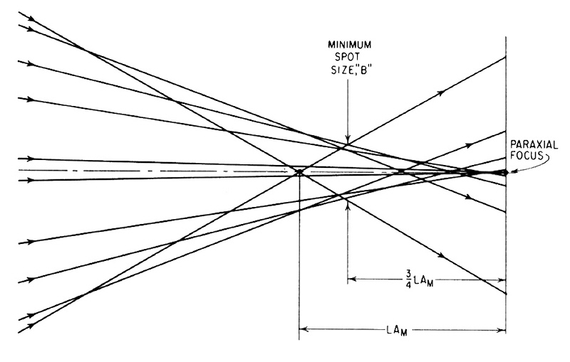
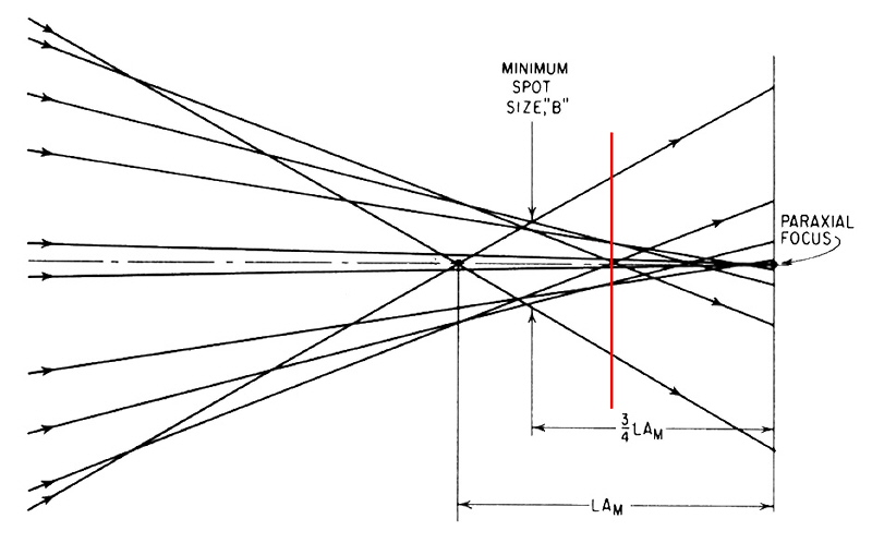
Next I will present a figure that accompanies this discussion:
The curve is a plot (typical) of the effect of spherical aberration as it pertains to rays at varying distances from the optical center (this being the vertical axis of the graph). The horizontal axis represents the amount by which the point of convergence of the rays at any distance differs from the point of convergence for rays that are infinitesimally away from the axis (the "paraxial" rays from which basic optical theory proceeds).
We note that the discrepancy increases as we consider rays further and further from the axis up to a point, and then declines as we go further yet, until at a certain distance from the axis there is no discrepancy. (If we go beyond that point, the discrepancy goes in the opposite direction, but this curve is cut off before we see much of that.)
Now, recognizing that the rays, from a given point on an object, that pass through various parts of our lens (that is, at different distances from the axis) do not all converge at the same place, how should we set the lens position (thinking in terms of a simple lens, focused by moving it, as in a view camera) to give the best image?
The answer is not simple. As we consider different candidate positions, we find that the "blur figure" caused by the lack of singular convergence changes. Its overall diameter changes, and we might think that the best focus setting would be when the overall diameter of the blur figure is the least.
But the variation of brightness as we go from the center of the blur figure also changes its nature as we use different focus settings. And when the overall diameter of the blur figure is the least, the "brighter" portion in its center is actually a bit larger, and so the blur figure appears relatively larger to the viewer.
Thus there is a "sweet spot" in which the apparent size of the blur figure to the viewer (and thus the degradation in sharpness) is the least. This can only be determined by subjective experimentation.
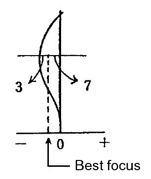
But commonly this "best focus setting" is one that moves the "paraxial" focus point toward the film or sensor by about 70% of the amount of the maximum spherical aberration.
And that is the significance of the numbers "3" and "7" on the figure (the relative lengths of certain distances), suggesting that the best focus is offset from the paraxial focus (0 on the horizontal axis) by 70% of the maximum spherical aberration.
This offset of the "target" focus from the paraxial focus is called the best focus adjustment (BFA).
Woof!
Now back to the discussion in the manual text. The passage I cited means that for any given lens design, the BFA value (possibly actually a table working from the focus setting for different distances) is written into the lens ROM. And further, that adjustments to this value (or perhaps to the entries in the table) for the specific lens "copy"are written into the lens ROM.
But what about in the field? At this time (1987) it was apparently not economical to equip field service centers with the gear to determine the best value (or table values), say, after a lens had been reassembled after replacing an element, and to write those new values into ROM.
So there is a much more agricultural provision for field adjustment.
A "pile-on" adjustment to the BFA value(s) can be made in the field by way of a two-bit number (four possible values) that is set by placing or removing solder bridges between two pairs of pads on the lens flexible circuit (one pair for each "bit").
Now, how was this "pile-on" adjustment to be determined?
Well, if the flexible circuit is being replaced, then the setting from the original circuit should be reconstructed. (This suggests that a setting of the "pile-on" adjustment was made at the factory, which does not match the overall story in the text, which suggests that everything at the factory is put into the lens ROM.)
If a certain element group has been replaced, then open both bridges (resulting in a certain one of the four possible values - apparently the default).
If other work is being done do nothing (leave the setting as found).
All amazing!
As you can tell, I can't get this whole story to fit together. But still, what we know gives us some insight into this matter.
Now, how this works for more modern lenses I have no idea.
Now, on to the use of the BFA value in the operation of the AF system.
The working of the AF detector essentially tells us how far the current focus setting of the lens differs from ideal focus in the geometric sense. That is, if the two subimages are aligned, then focus would be ideal on a paraxial basis (ignoring the impact of spherical aberration on the truly ideal focus setting).
So before the findings of the AF detector are utilized, the lens is asked to provide the BFA value applicable to the current lens focus setting and that is used to adjust the findings of the AF detector before that result is used to guide the AF process.
Best regards,
Doug
Sadly, most of the information I have on the subject is gleaned from a rather old publication, the Canon service manual for the Canon EF 50 mm f/1.8, 28 mm f/2.8, and 15 mm f/2.8 lenses (1987). Certainly the implementation of the concepts I discuss here may be much different for newer lenses, and in addition there are further complexities in the case of zoom lenses.
But the underlying concepts comport well with discussion of the theoretical underpinnings in various optical textbooks.
I cite here a passage that recurs for all three lenses:
There is bound to be some discrepancy between the focus point determined by
the autofocus system and the actual best focus point of the interchangeable lenses
due to the inherent differences between the different lens types.
In the EOS system, the difference between the AF focus and the optical best
focus has been determined for each lens type and the information written into
the lenses Read Only Memory (ROM) so that correction for the difference at
maximum aperture is made electronically.
In actuality, in addition to this type difference, there is a difference between
individual lenses within each type, which can be noticeable if not corrected, At
the factory, correction is written into the individual lens' ROM with a expensive,
special tool. This is called the "Best Focus Adjustment". Because of the
tooling cost involved, this adjustment will not be a part of the service procedure.
In its stead, the following actions will be taken.
Next I will present a figure that accompanies this discussion:
The curve is a plot (typical) of the effect of spherical aberration as it pertains to rays at varying distances from the optical center (this being the vertical axis of the graph). The horizontal axis represents the amount by which the point of convergence of the rays at any distance differs from the point of convergence for rays that are infinitesimally away from the axis (the "paraxial" rays from which basic optical theory proceeds).
This curve is for a lens that has been "corrected" for spherical aberration, and in effect shows the "residual" aberration. For an uncorrected lens, the aberration continues to increase (in an "accelerating" way, in fact) as we consider rays further and further from the axis.
We note that the discrepancy increases as we consider rays further and further from the axis up to a point, and then declines as we go further yet, until at a certain distance from the axis there is no discrepancy. (If we go beyond that point, the discrepancy goes in the opposite direction, but this curve is cut off before we see much of that.)
Now, recognizing that the rays, from a given point on an object, that pass through various parts of our lens (that is, at different distances from the axis) do not all converge at the same place, how should we set the lens position (thinking in terms of a simple lens, focused by moving it, as in a view camera) to give the best image?
The answer is not simple. As we consider different candidate positions, we find that the "blur figure" caused by the lack of singular convergence changes. Its overall diameter changes, and we might think that the best focus setting would be when the overall diameter of the blur figure is the least.
But the variation of brightness as we go from the center of the blur figure also changes its nature as we use different focus settings. And when the overall diameter of the blur figure is the least, the "brighter" portion in its center is actually a bit larger, and so the blur figure appears relatively larger to the viewer.
Thus there is a "sweet spot" in which the apparent size of the blur figure to the viewer (and thus the degradation in sharpness) is the least. This can only be determined by subjective experimentation.
But commonly this "best focus setting" is one that moves the "paraxial" focus point toward the film or sensor by about 70% of the amount of the maximum spherical aberration.
And that is the significance of the numbers "3" and "7" on the figure (the relative lengths of certain distances), suggesting that the best focus is offset from the paraxial focus (0 on the horizontal axis) by 70% of the maximum spherical aberration.
This offset of the "target" focus from the paraxial focus is called the best focus adjustment (BFA).
Woof!
Now back to the discussion in the manual text. The passage I cited means that for any given lens design, the BFA value (possibly actually a table working from the focus setting for different distances) is written into the lens ROM. And further, that adjustments to this value (or perhaps to the entries in the table) for the specific lens "copy"are written into the lens ROM.
But what about in the field? At this time (1987) it was apparently not economical to equip field service centers with the gear to determine the best value (or table values), say, after a lens had been reassembled after replacing an element, and to write those new values into ROM.
So there is a much more agricultural provision for field adjustment.
A "pile-on" adjustment to the BFA value(s) can be made in the field by way of a two-bit number (four possible values) that is set by placing or removing solder bridges between two pairs of pads on the lens flexible circuit (one pair for each "bit").
Now, how was this "pile-on" adjustment to be determined?
Well, if the flexible circuit is being replaced, then the setting from the original circuit should be reconstructed. (This suggests that a setting of the "pile-on" adjustment was made at the factory, which does not match the overall story in the text, which suggests that everything at the factory is put into the lens ROM.)
If a certain element group has been replaced, then open both bridges (resulting in a certain one of the four possible values - apparently the default).
If other work is being done do nothing (leave the setting as found).
All amazing!
As you can tell, I can't get this whole story to fit together. But still, what we know gives us some insight into this matter.
Now, how this works for more modern lenses I have no idea.
Now, on to the use of the BFA value in the operation of the AF system.
The working of the AF detector essentially tells us how far the current focus setting of the lens differs from ideal focus in the geometric sense. That is, if the two subimages are aligned, then focus would be ideal on a paraxial basis (ignoring the impact of spherical aberration on the truly ideal focus setting).
So before the findings of the AF detector are utilized, the lens is asked to provide the BFA value applicable to the current lens focus setting and that is used to adjust the findings of the AF detector before that result is used to guide the AF process.
Best regards,
Doug