
-
Please use real names.
Greetings to all who have registered to OPF and those guests taking a look around. Please use real names. Registrations with fictitious names will not be processed. REAL NAMES ONLY will be processed
Firstname Lastname
Register
We are a courteous and supportive community. No need to hide behind an alia. If you have a genuine need for privacy/secrecy then let me know! -
Welcome to the new site. Here's a thread about the update where you can post your feedback, ask questions or spot those nasty bugs!
You are using an out of date browser. It may not display this or other websites correctly.
You should upgrade or use an alternative browser.
You should upgrade or use an alternative browser.
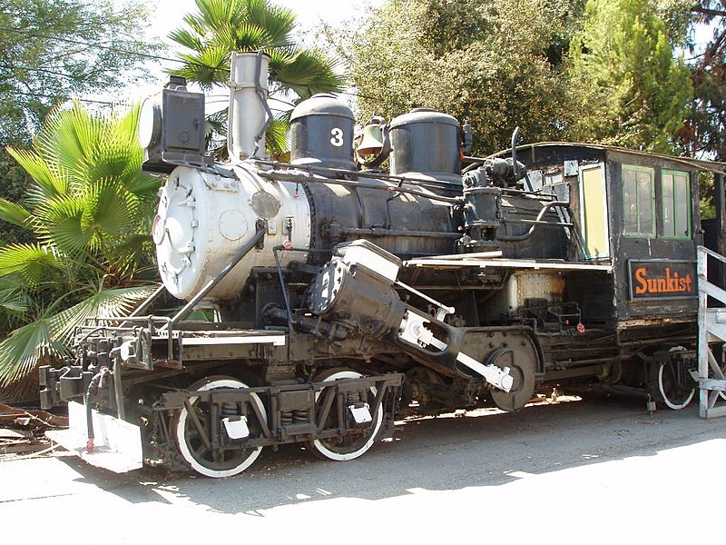
Who likes steam locomotives?
- Thread starter Asher Kelman
- Start date

Doug Kerr
Well-known member
Hi, Stuart,
Lovely!
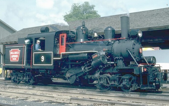
Probably a "two-truck" (8 driven wheels), as I don't see the spur gear pair just behind the engine that drives an upper rear shaft leading to the "tender" truck.
Shay.
Lovely. Note that here all the driven axles are driven directly through (way fat) bevel gears, no side rods involved.
The Shay is really the mother of all geared locomotives (perhaps also the most common).
Thanks so much.
Best regards,
Doug
There was another Heisler, this time with the rear drive shaft in place, but with the front, driveshaft and con-rods missing.
Lovely!
Probably a "two-truck" (8 driven wheels), as I don't see the spur gear pair just behind the engine that drives an upper rear shaft leading to the "tender" truck.
There was also a 3 cylinder gear driven Shey, also with the driveshafts missing.
Shay.
Lovely. Note that here all the driven axles are driven directly through (way fat) bevel gears, no side rods involved.
The Shay is really the mother of all geared locomotives (perhaps also the most common).
Thanks so much.
Best regards,
Doug


Doug Kerr
Well-known member
Hi, Stuart,
Yes, on a Shay you can't tell from the view I had. On a Shay, the rear drive shaft to the second truck just continues on to the third truck if it is powered. Thus there is no special stuff needed near the engine for that situation.
In a Heisler, the drive shafts only go to the "near" axle of the first and second trucks, so the drive shaft to the second truck can't continue to the third truck (it couldn't get past the second axle of the second truck).
So if the third truck is to be powered, there has to be a spur gear setup just behind the engine to drive a second (and higher) rearward shaft that goes (above the second truck) to the third (tender) truck (there is a universal joint there to allow the shaft to angle down to the front axle of the tender truck).
Best regards,
Doug
The Shay was a 3 trucker . . .
Yes, on a Shay you can't tell from the view I had. On a Shay, the rear drive shaft to the second truck just continues on to the third truck if it is powered. Thus there is no special stuff needed near the engine for that situation.
In a Heisler, the drive shafts only go to the "near" axle of the first and second trucks, so the drive shaft to the second truck can't continue to the third truck (it couldn't get past the second axle of the second truck).
So if the third truck is to be powered, there has to be a spur gear setup just behind the engine to drive a second (and higher) rearward shaft that goes (above the second truck) to the third (tender) truck (there is a universal joint there to allow the shaft to angle down to the front axle of the tender truck).
All lovely. Thanks so much. I'll see what I can identify. I'm not really a locomotive expert at all. (Everything I know about the Heisler I learned since you showed a picture of what turned out to be one - I had never heard of it before that.)There were lots more, and at the risk of outstaying my welcome, here are a few of them.
Best regards,
Doug


Doug Kerr
Well-known member
Hi, Stuart,
Thanks so much.
Best regards,
Doug
Lovely.Well, here's some info about the Shay and #924.
Thanks so much.
Best regards,
Doug
Doug Kerr
Well-known member
This figure from Heisler's patent on the four-cylinder version of his locomotive shows the spur gear arrangement for driving the third (tender) truck (gears 45, 46):
(The patent on the basic two-cylinder locomotive illustrates a two-truck version.)
I had said that the drive shafts drive the near axles on the trucks; in fact, they drive the far axles (front axle of the first truck, rear axles of the second and third trucks).
Best regards,
Doug
(The patent on the basic two-cylinder locomotive illustrates a two-truck version.)
I had said that the drive shafts drive the near axles on the trucks; in fact, they drive the far axles (front axle of the first truck, rear axles of the second and third trucks).
Best regards,
Doug
Doug Kerr
Well-known member
In the Heisler locomotive, some clever attention had to be taken to the gearing.
This figure (adapted from a figure in Heisler's patent covering a four-cylinder locomotive but which also introduces the method of driving of the third truck) is a view of the second (rear) truck from above, and shows the bevel gear arrangement by which the first rear drive shaft drives the rear axle of the second truck:
The drive shaft arrives from the right, and is shown starting at the point highlighted by the elliptical outline.
The bevel gear arrangement, incidentally, is enclosed, a more desirable situation than the open bevel gearing used on the Shay locomotive (where the gears can suffer from the intrusion of sand and dirt, and where suitable lubrication is hard to maintain).
Hear, I have adapted that same figure to show the arrangement needed at the first (forward) truck:
Note the mirror image arrangement of the bevel gearing, needed to produce the proper rotation of the driven axle (consistent with that for the second truck), given that both drive shafts rotate in the same direction.
The third truck (tender) is in the same situation as the second truck, but its drive shaft rotates in the opposite direction (owing to its being driven from the engine crankshaft through spur gears). Accordingly, still another orientation of the bevel gearing is required to give proper rotation of the driven axle, as shown in this adaptation of the original figure:
These subtleties are not illuminated in the patent.
A similar situation exists in the Shay locomotive, but there the faces of the driven bevel gears must must all face the same way (to the outside of the locomotive - generally to the right). Thus the proper "sense" of axle rotation needed at the various trucks is obtained by having the driving gears there engage the driven gears always on their forward sides, which for the first truck is the far side and for the second (and third, if applicable) is the near side. (We can see vestiges of the first truck manifestation of this on Stuart's photo of the Shay locomotive, although the drive shaft itself and I think the driving bevel gears as well are gone there.)
Without benefit of the preceding explanation, one might wonder why go to the trouble of supporting the drive shaft so far as to allow the driving gears to engage the driven gears at their front sides, but we have just seen that this has to be done on one or two of the trucks in any case. By making this the front truck, this additional need only occurs on one of the three trucks in a three-truck locomotive.
We can see the complete arrangement on a three-truck Shay locomotive in this photo:

Leonard G: Three-truck Shay locomotive "Sonora"
This is all bush-league mechanical engineering, but you would be amazed at the number of "oh shits" that have occurred in first models of such mechanisms! There have been many similar things in electrical engineering projects.
Best regards,
Doug
This figure (adapted from a figure in Heisler's patent covering a four-cylinder locomotive but which also introduces the method of driving of the third truck) is a view of the second (rear) truck from above, and shows the bevel gear arrangement by which the first rear drive shaft drives the rear axle of the second truck:
Heisler second truck drive
The drive shaft arrives from the right, and is shown starting at the point highlighted by the elliptical outline.
The bevel gear arrangement, incidentally, is enclosed, a more desirable situation than the open bevel gearing used on the Shay locomotive (where the gears can suffer from the intrusion of sand and dirt, and where suitable lubrication is hard to maintain).
Hear, I have adapted that same figure to show the arrangement needed at the first (forward) truck:
Heisler first truck drive
Note the mirror image arrangement of the bevel gearing, needed to produce the proper rotation of the driven axle (consistent with that for the second truck), given that both drive shafts rotate in the same direction.
The third truck (tender) is in the same situation as the second truck, but its drive shaft rotates in the opposite direction (owing to its being driven from the engine crankshaft through spur gears). Accordingly, still another orientation of the bevel gearing is required to give proper rotation of the driven axle, as shown in this adaptation of the original figure:
Heisler third truck drive
These subtleties are not illuminated in the patent.
A similar situation exists in the Shay locomotive, but there the faces of the driven bevel gears must must all face the same way (to the outside of the locomotive - generally to the right). Thus the proper "sense" of axle rotation needed at the various trucks is obtained by having the driving gears there engage the driven gears always on their forward sides, which for the first truck is the far side and for the second (and third, if applicable) is the near side. (We can see vestiges of the first truck manifestation of this on Stuart's photo of the Shay locomotive, although the drive shaft itself and I think the driving bevel gears as well are gone there.)
Without benefit of the preceding explanation, one might wonder why go to the trouble of supporting the drive shaft so far as to allow the driving gears to engage the driven gears at their front sides, but we have just seen that this has to be done on one or two of the trucks in any case. By making this the front truck, this additional need only occurs on one of the three trucks in a three-truck locomotive.
We can see the complete arrangement on a three-truck Shay locomotive in this photo:
Leonard G: Three-truck Shay locomotive "Sonora"
From Wikipedia: public domain
This is all bush-league mechanical engineering, but you would be amazed at the number of "oh shits" that have occurred in first models of such mechanisms! There have been many similar things in electrical engineering projects.
Best regards,
Doug
Doug Kerr
Well-known member
Stuart Rae, traveling far from home in the American Pacific Northwest, through one of his always-interesting photographs, introduced me to the Heisler geared steam locomotive, with which I had not previously been familiar. Later, Stuart added some photos of the Shay geared locomotives. This all led to a series of discussions from me of the mechanisms of these machines.
By way of completing the circle, I will here briefly mention the third of the three most important types of geared steam locomotive, the Climax locomotive. (How appropriate!)
Here we see a lovely shot of a class B Climax locomotive of the later design of that class:
Photographer unknown: Class B two-truck Climax geared locomotive
From the Geared Steam Locomotive Works Web site
The later Type B Climax and the Type C Climax locomotive had two inclined steam cylinders. They drove a cross shaft which, through either skew or hypoid bevel gearing, drove a longitudinal drive shaft. This in turn, through other sets of skew or hypoid bevel gears, drove both axles of the two or three driven trucks (two in the class B, three in the class C).
Universal joints were provided in the drive shaft to allow for the articulation of the trucks.
On the class C version, a tender sat on the third driven truck.I believe that in that case the "box" behind the cab was the water tank, the tender being for fuel only.
The catalog of the Climax Manufacturing Company for the Climax geared locomotive (date yet unknown) includes this lovely passage:
Best regards,
Doug
By way of completing the circle, I will here briefly mention the third of the three most important types of geared steam locomotive, the Climax locomotive. (How appropriate!)
Here we see a lovely shot of a class B Climax locomotive of the later design of that class:
Photographer unknown: Class B two-truck Climax geared locomotive
From the Geared Steam Locomotive Works Web site
The later Type B Climax and the Type C Climax locomotive had two inclined steam cylinders. They drove a cross shaft which, through either skew or hypoid bevel gearing, drove a longitudinal drive shaft. This in turn, through other sets of skew or hypoid bevel gears, drove both axles of the two or three driven trucks (two in the class B, three in the class C).
Hypoid bevel gearing, the type found in many rear-wheel drive auto differentials and most truck differentials, and its simpler cousin, skew bevel gearing, allows the input shaft to be in a different plane than the output shaft. Thus, in this case, it allows the longitudinal drive shaft to be continuous across all the driven axle shafts (and in fact the engine shaft as well.)
Universal joints were provided in the drive shaft to allow for the articulation of the trucks.
On the class C version, a tender sat on the third driven truck.I believe that in that case the "box" behind the cab was the water tank, the tender being for fuel only.
The catalog of the Climax Manufacturing Company for the Climax geared locomotive (date yet unknown) includes this lovely passage:
The locomotive is equipped complete with all tools and fittings for its operation, including steam brake, steam syphon and suction hose for taking water, two injectors, sight feed lubricator, water gauge try cocks, steam gauge headlight, bell, whistle, pop valve, machinist hammer, pipe wrench, monkey wrench, chisel, punch, oil cans, clinker bar and poker. It is painted, varnished, lettered and numbered as desired.
Best regards,
Doug
Last edited:
Doug Kerr
Well-known member
In this lovely illustration from the Climax locomotive catalog (date unknown), we see a typical Climax driven truck:
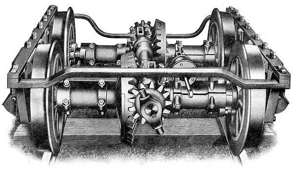
Note the "mirror image" arrangement of the skew bevel gear sets (used here rather than the more efficient hypoid bevel gears thought to be used in later versions). This is presumably to allow the pinons to both be "outboard", probably to cater to a better arrangement of the local shaft bearings. The gear sets are not enclosed (normal for a Climax locomotive).
We see on the near side one half of the near-side universal joint (cross type, just as usually used in rear-wheel drive automobiles).
We also see the brake cylinder for the truck (but not any of the brake mechanism beyond that).
Neat stuff.
How about those technical illustrators, eh?
Best regards,
Doug
Doug Kerr
Well-known member
It appears that perhaps all Climax locomotives used skew bevel gears rather than hypoid bevel gears, and the mentions of hypoid bevel gears were wholly incorrect.
It may be that the person(s)responsible had only seen the hypoid form of non-coplanar axis bevel gearing and assumed that was what was used in the Climax machines.
Best regards,
Doug
It may be that the person(s)responsible had only seen the hypoid form of non-coplanar axis bevel gearing and assumed that was what was used in the Climax machines.
Best regards,
Doug
Dawid Loubser
Member
Doug and Stuart, thank you for the wonderfully detailed information and pictures on types of Locomotives that we never had over here in Africa - fascinating reading. Since childhood the Shay Locomotives have always fascinated me, but I never even knew of the other two types of geared engines.
I don't have anything to contribute to this thread at the moment, other than two extra images from the inside of the GEA Garratt that I posted about earlier:
(Olympus OM-3Ti, Zuiko 21mm f/2.0, Kodak TMY400-2 film)
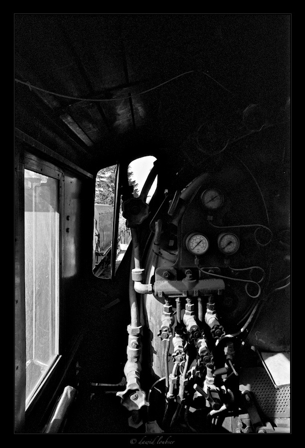
(Olympus OM-3Ti, Zuiko 21mm f/2.0, Kodak TMY400-2 film)
I don't have anything to contribute to this thread at the moment, other than two extra images from the inside of the GEA Garratt that I posted about earlier:
(Olympus OM-3Ti, Zuiko 21mm f/2.0, Kodak TMY400-2 film)
(Olympus OM-3Ti, Zuiko 21mm f/2.0, Kodak TMY400-2 film)
Doug Kerr
Well-known member
Hi, Dawid,
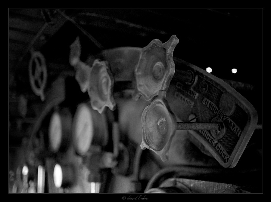
As a matter of technical interest, the valve handle on the far right in the first pic is labeled (in English) "cylinder cock". Cylinder cocks are valves (there is at least one at each end of each cylinder) used to bleed accumulated waters(steam that has condensed in place) from the cylinder to the atmosphere. It is this operation that results in the streams of visible vapor issuing from the cylinder area when a locomotive is about to get underway and in fact for the first little while as it is moving.
If this water was not released, then during the "compression" part of the cycle (yes, the steam locomotive engine cycle has a compression phase - not useful, as in an internal combustion engine, but rather a side effect of practical valve systems) the water, being incompressible, would block piston motion (suddenly, possibly with the consequence of damage to the machine).
This arrangement seems to be for a "direct" cylinder cock system - the motion of the handle is conducted by a system of long shafts connected by gearboxes and/or universal joints to the valve itself, which is at the cylinder.
Many locomotives have power cylinder cocks. Here, the valves themselves are worked by small double-acting cylinders driven by compressed air or steam. They are controlled by lever-operated control valves in the cab. This eliminates the complicated mechanical arrangement, and in fact allows a more robust valve to be used.
I was unable to make out the marking on the second handle. I suspect the third one is the second cylinder cock for this side (cylinder).
I have to reflect some more on the interesting set of stuff shown in the second photo.
Again, thanks so much for these great pix.
Best regards,
Doug
Striking photos. They so seem to capture the overall world of the classical steam locomotive.Doug and Stuart, thank you for the wonderfully detailed information and pictures on types of Locomotives that we never had over here in Africa - fascinating reading. Since childhood the Shay Locomotives have always fascinated me, but I never even knew of the other two types of geared engines.
I don't have anything to contribute to this thread at the moment, other than two extra images from the inside of the GEA Garratt that I posted about earlier:
As a matter of technical interest, the valve handle on the far right in the first pic is labeled (in English) "cylinder cock". Cylinder cocks are valves (there is at least one at each end of each cylinder) used to bleed accumulated waters(steam that has condensed in place) from the cylinder to the atmosphere. It is this operation that results in the streams of visible vapor issuing from the cylinder area when a locomotive is about to get underway and in fact for the first little while as it is moving.
If this water was not released, then during the "compression" part of the cycle (yes, the steam locomotive engine cycle has a compression phase - not useful, as in an internal combustion engine, but rather a side effect of practical valve systems) the water, being incompressible, would block piston motion (suddenly, possibly with the consequence of damage to the machine).
This arrangement seems to be for a "direct" cylinder cock system - the motion of the handle is conducted by a system of long shafts connected by gearboxes and/or universal joints to the valve itself, which is at the cylinder.
Many locomotives have power cylinder cocks. Here, the valves themselves are worked by small double-acting cylinders driven by compressed air or steam. They are controlled by lever-operated control valves in the cab. This eliminates the complicated mechanical arrangement, and in fact allows a more robust valve to be used.
I was unable to make out the marking on the second handle. I suspect the third one is the second cylinder cock for this side (cylinder).
I have to reflect some more on the interesting set of stuff shown in the second photo.
Again, thanks so much for these great pix.
Best regards,
Doug
Last edited:
Dawid Loubser
Member
Hi Doug,
I believe the second valve you see is the Ejector valve. I am glad you like my images - the last two that I have posted are a bit more "boring" than the rest, but film is hard work either way. The Zuiko 21mm f/2.0 is an extraordinary lens for capturing these sort of images (on 35mm film, in anyway - steam engines just cry out for larger formats, most of the time).
Thank you for your explanation of the Cylinder Cock valve (I should have added that)!
scott kirkpatrick
Member
Three working geared locomotives in Cass WV
Just noticed this thread. A few years ago I was in West Virginia and went to see the geared engines at Cass. They have 5 or 6 engines from coal mining service, of which two Shays and (I believe) one Climax are in regular operation, and the wreck of a Heisler is also awaiting further restoration. Here are the running examples:
 Two Shays
 and the Climax.
Doug do you recognize these?
Scott
Just noticed this thread. A few years ago I was in West Virginia and went to see the geared engines at Cass. They have 5 or 6 engines from coal mining service, of which two Shays and (I believe) one Climax are in regular operation, and the wreck of a Heisler is also awaiting further restoration. Here are the running examples:
Doug do you recognize these?
Scott
scott kirkpatrick
Member
some details from the Cass WV locomotives
The flex coupling for the Shay's driveshaft:

and a close-up of the drive cylinders on the #4 Shay:

scott
The flex coupling for the Shay's driveshaft:
scott
Doug Kerr
Well-known member
Hi, Scott,
Lovelyl Thanks so much.
I think that is the Heisler.
A Climax looks like this:
I know that line is often quoted in connection with geared locomotives.
Thanks again.
Best regards,
Doug
Lovelyl Thanks so much.
and the Climax.
I think that is the Heisler.
A Climax looks like this:
Doug do you recognize these?
I know that line is often quoted in connection with geared locomotives.
Thanks again.
Best regards,
Doug
scott kirkpatrick
Member
Cass, Climax and Heisler
The Cass operation is a West Virginia state park. There is a very interesting website with details, history (both of the original line and of the restoration efforts) at http://www.cassrailroad.com, and more pictures. Heisler #6 (in my picture) was the last Heisler locomotive sold, and apparently ran on the west coast. Cass was a lumber operation, and the various rail lines that existed were all owned or controlled by the West Virginia Pulp and Paper Co. According to the website, they are making progress on restoring the Climax, which was a pile of parts when I visited in 2008. They now have 12 miles of line restored and used in their tourist operations.
The geared engines are really slow, but carry enormous loads single-handed down twisty narrow-guage tracks usually to a mill at the road's end. The Cass mill was also enormous, but burned down leaving only a (picturesque) ruin:

The Green Bank radio telescope provides some employment to this part of WV, but most of its 20th century history seems to be receding into the mist, like this drive-in:

The classic images that I have in my head from O W Link's pictures of the Norfolk and Western line's Pocahontas routes (the county that Cass is in) are hard to find today. Next time I get to that area, I will try to visit Iaeger and locate the site of the Drive-in picture he took there. A rephotographic study showing the former drive-in site and a diesel freight hustling along the background with a hundred or so coal cars would be a great trophy. Now where can I get ahold of a Buick Roadmaster convertible to fix in the foreground...?
Google maps shows no trace of the drive-in site, but the tracks are still there, with mile-long coal car trains parked on several of them.
scott
The Cass operation is a West Virginia state park. There is a very interesting website with details, history (both of the original line and of the restoration efforts) at http://www.cassrailroad.com, and more pictures. Heisler #6 (in my picture) was the last Heisler locomotive sold, and apparently ran on the west coast. Cass was a lumber operation, and the various rail lines that existed were all owned or controlled by the West Virginia Pulp and Paper Co. According to the website, they are making progress on restoring the Climax, which was a pile of parts when I visited in 2008. They now have 12 miles of line restored and used in their tourist operations.
The geared engines are really slow, but carry enormous loads single-handed down twisty narrow-guage tracks usually to a mill at the road's end. The Cass mill was also enormous, but burned down leaving only a (picturesque) ruin:
The Green Bank radio telescope provides some employment to this part of WV, but most of its 20th century history seems to be receding into the mist, like this drive-in:
The classic images that I have in my head from O W Link's pictures of the Norfolk and Western line's Pocahontas routes (the county that Cass is in) are hard to find today. Next time I get to that area, I will try to visit Iaeger and locate the site of the Drive-in picture he took there. A rephotographic study showing the former drive-in site and a diesel freight hustling along the background with a hundred or so coal cars would be a great trophy. Now where can I get ahold of a Buick Roadmaster convertible to fix in the foreground...?
Google maps shows no trace of the drive-in site, but the tracks are still there, with mile-long coal car trains parked on several of them.
scott
Last edited:
Doug Kerr
Well-known member
Hi, Scott,
Thanks for the further insight.
Wondrous photos, all.
Best regards,
Doug
Thanks for the further insight.
Wondrous photos, all.
Best regards,
Doug
Asher Kelman
OPF Owner/Editor-in-Chief
Just noticed this thread. A few years ago I was in West Virginia and went to see the geared engines at Cass. They have 5 or 6 engines from coal mining service, of which two Shays and (I believe) one Climax are in regular operation, and the wreck of a Heisler is also awaiting further restoration. Here are the running examples:
Two Shays
and the Climax.
Doug do you recognize these?
Scott
This thread is glorious! There must be superb steam trains still going in Australia, the U.K. the European continent. Looking forward to more of these charming monsters!
Asher
")
Don't miss out on Stuart Rae's veteran locomotive from the U.K., here
Jarmo Juntunen
Well-known member
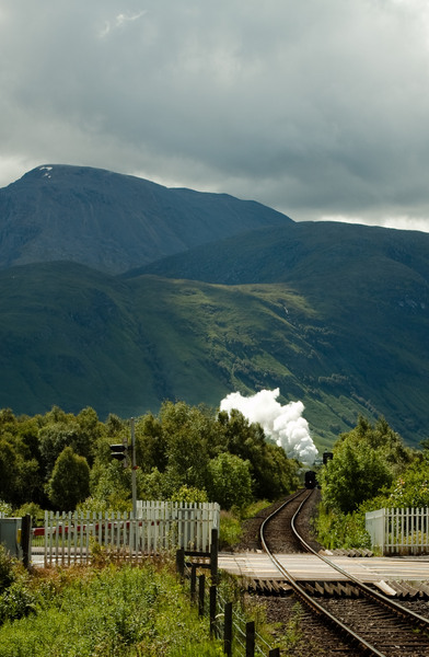
Indeed there are, Asher! Here's the Jacobite leaving Mallaig towards Ft William (Scotland):
Jarmo Juntunen
Well-known member
...and here she is again, this time with Ben Nevis:
Jarmo Juntunen
Well-known member
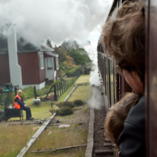
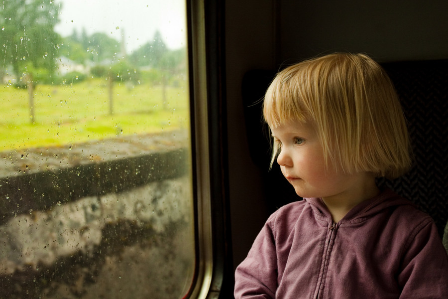
However, my personal favourite Jacobite themed picture is this one (sorry, this is a repost but oh well):
Laura Aboard the Jacobite
Asher Kelman
OPF Owner/Editor-in-Chief
Fabulous boost Michael Nagel for finding this treasure for us all!

Jarmo Juntunen: Laura Aboard the Jacobite
Asher
Jarmo Juntunen: Laura Aboard the Jacobite
Asher
Asher Kelman
OPF Owner/Editor-in-Chief
Doug Kerr
Well-known member
I don't recognize that locomotive.
Best regards,
Doug
Best regards,
Doug
Asher Kelman
OPF Owner/Editor-in-Chief
You have to imagine it. We must show the happiness of the passengers too, LOL!I don't recognize that locomotive.
Best regards,
Doug
Doug Kerr
Well-known member
This is one of my favorite locomotives, also a 2-8-0 "Consolidation" on display:

Douglas A. Kerr: 2-8-0 Consolidation, Frisco, Texas
A lot of the story of this locomotive, and the wonderful 2011 event that introduced me to her, is found in this OPF thread:
https://openphotographyforums.com/forums/threads/a-lovely-wedding-in-frisco-texas.14878/post-121619
That notwithstanding, I though I would repeat here a slightly different version one of what I think is one of the most precious shots from that event, this of two of Carla's great-granddaughters (the event was their mother's second wedding).

Douglas A. Kerr: Two bridesmaids
Best regards.
Doug
Douglas A. Kerr: 2-8-0 Consolidation, Frisco, Texas
A lot of the story of this locomotive, and the wonderful 2011 event that introduced me to her, is found in this OPF thread:
https://openphotographyforums.com/forums/threads/a-lovely-wedding-in-frisco-texas.14878/post-121619
That notwithstanding, I though I would repeat here a slightly different version one of what I think is one of the most precious shots from that event, this of two of Carla's great-granddaughters (the event was their mother's second wedding).
Douglas A. Kerr: Two bridesmaids
Best regards.
Doug
Last edited:
Asher Kelman
OPF Owner/Editor-in-Chief
Beautiful girls versus a fabulous giant machine!
But tell us, how come it became a wedding location?
Asher
But tell us, how come it became a wedding location?
Asher